I am a  master candidate at Georgetown University, enrolled in the Communication, Culture, and Technology program (STEM base) who is going to graduate in May 2025. My career path’s been a colorful mix, touching diverse fields such as program management, (social media) marketing, journalism, and finance. Currently, I am is seeking for data-related jobs with a passion for social issues such as environmental participation (click here to see my Avatar), entertainment (I am also a stand-up and improv comic!), childcare, and gender equality. 

Venturing into grad school, I have willingly stepped outside my comfort zone to acquire technical skills, such as visual design (Adobe Suite, Capcut, Canva, Miro), data processing (MySQL, Tableau, Excel Sheet, Look Studio, RStudio, RAWGraphs), Website Construction (WordPress, Elementor, Figma), CRM platform like Salesforce and hands-on skills like 3D printing.

Enrolling in this course is an exciting opportunity for me to develop practical, hands-on skills like CAD and woodworking—areas I’ve never been familiar with. Although I’m all thumbs when it comes to crafting, I’ve always been deeply curious about this field. I’m eager to learn these techniques and work on projects that genuinely inspire me. During my first semester in CCT, I had the chance to explore 3D printing and create an avatar called ‘Masked-Lung,’ inspired by my academic interest in environmental issues (see below). By taking this class, I hope to create more fascinating projects like that!

Orthographic Drawing

Explain your process for analyzing and drawing the object:
To measure the object, I started by searching for the product online and contacting customer service to confirm the actual dimensions. While drawing the product, I gave extra thought to the annotations, especially regarding the measurement units. Initially uncertain, I experimented and realized that millimeters made more sense than centimeters for this task.

Reflect on any challenges and what you learned during the assignment:
As a stand-up comic and debater, the microphone has been an integral part of my life, but I’ve never paid attention to its actual size, and I definitely don’t own one at home. This made measuring the microphone as challenging as any other unfamiliar object. Through this assignment, I got the chance to closely examine a tool that has been so important to my hobbies for the past decade. It was fascinating to discover the variety of microphones available when I Googled them—handheld (both wired and wireless), ear-hook, clip-on, and more. Each type has unique features that I had never noticed before. This experience has made me more observant and appreciative of the gadgets I use in everyday life.

Wooden Bottle Holder Design and Construction

I set out to create a single-bottle stand with the concept of an art exhibition in mind, rather than just a simple container to hold a bottle. After extensive research, I discovered a design that strikes a balance between aesthetic appeal and functionality (as shown in Figure 1). 

However, the primary focus of this assignment is woodworking, while the reference design clearly incorporates metal components. My first challenge, therefore, was figuring out how to replace the metal connectors and support structures with wood. To address this, I substituted the metal support plates with a single wooden panel. This not only provided stability but also minimized the amount of cutting required for the four frame edges.

The next challenge was cutting four rectangular wooden beams. Most of the available workshop materials were large solid wood pieces, making it difficult to cut precise rectangular beams with square bases. Additionally, to properly support the wine bottle, the beams needed to be symmetrical on both sides, requiring a high level of precision. To overcome this, I opted to use cylindrical pieces instead of rectangular beams.

However, this introduced a third challenge: securing the cylindrical wood for cutting, as it tends to roll. I solved this by using the wood clamps fixed to the workbench in the workshop, allowing for smooth and accurate cuts.

The final challenge was assembling and securing the wooden components. Initially, I attempted to attach the cylinders to the baseboard using a nail gun, but the cylinders spun uncontrollably, making it impossible to drive in the nails. In the end, I temporarily secured the pieces with wood glue before nailing them in place.

And with that, my final product came to life!

Custom Laser-Cut Design

I wanted to explore a flexible, foldable design, and Festi’s Box Maker proved to be an excellent resource. I found a basic template on the website, but it required some modifications.

First, the line colors were incorrect—I needed to change all Vector Cutting sections to RGB red and adjust the stroke thickness accordingly. Additionally, I engraved my name onto the piece using Raster Engraving.

For the first version, I aimed for a seamless closure without the protruding locking mechanisms from the original template. To achieve this, I used the “Click to Minus Front” function in Pathfinder to remove the locking parts and deleted any unnecessary latch structures.

However, the initial prototype had a significant flaw: the panels didn’t fit together tightly. Worse still, when I attempted to assemble the box, the wooden pieces cracked under the pressure of hammering them into place.

For the second iteration, I made a few critical adjustments. First, I removed the two small decorative cutouts at the top. Then, I eliminated the interlocking edges on three sides that were meant to slot into the base, opting instead to glue the structure together. Once the second version was assembled, I used sandpaper to smooth the edges of the opening, ensuring a snug and secure fit.

With that, my laser-cut project was successfully completed!

What inspired your chess piece designs?
The base of my chess pieces follows a classic structure: a cylinder at the bottom, two cones with different slopes in the middle, and two cylinders of varying radius at the top. For the decorative element at the top, designed for easy hand-holding, I drew inspiration from the Raja (King), a traditional chess piece. Additionally, since my last name starts with “K,” I incorporated the letter “K” as a distinctive design feature. The heart shape was chosen for its ergonomic form, making it easier to pick up the pieces.

What challenges did you face in designing for 3D printing?
The first version of my chess pieces was too small, making the top designs unrecognizable at that scale. Additionally, they were fragile and prone to breaking. The base of the pieces was also too short. To address these issues, I increased the overall size—expanding the base cylinder radius from 25mm to 40mm, adjusting the middle cones from 16.2mm to 36.2mm, and increasing the height of all the pieces. The second version closely resembles standard chess pieces, with discernible and sturdier top designs.

How did you address overhangs, supports, and print orientation?
I used an FDM (Ultimaker 3D Printer) and added tree supports for the second version of my chess pieces. The first version was too small to require supports. The layer resolution differences between the two versions were also noticeable. The first version was printed in Fast mode (0.2mm), resulting in more visible layer lines, whereas the second version was printed in Normal mode (0.15mm), achieving a much smoother finish.

Fusion 360 Custom Modeling

I started by constructing the key’s head, using a fitted spline to draw the left half of a heart. My first challenge arose when I realized we had only learned how to extrude or revolve shapes in class, but not how to mirror and merge lines into a symmetrical heart. Instead of redrawing the right half manually, I found an axis rotation option in the settings and overlapped two intersection points to create a complete blue heart shape (the blue color indicates that it is a shape rather than just 2 lines).

After extruding it into a solid, I used fillet and shell functions to smooth the edges for a comfortable grip. Next, I sketched a circle at the heart’s base, extruded it into a cylinder for the handle, refined its edges, and joined it with the key head.

To build the blade, I rotated the key horizontally and sketched two circles on the handle, duplicating them with a rectangular array. However, the cylinders generated along the coordinate axis instead of the handle. Aligning them was tricky—I moved the first manually and adjusted the extrusion direction for the second by entering a negative value.

Designing and Building an Automaton

Initial Vision

My initial concept was to create a round stage with a spinning platform on its surface, featuring two characters—representing myself and my soul—standing on it. When the gear is turned, the platform would rotate like a merry-go-round. The stage is divided by a curtain, separating it into “debate” mode and “comedy” mode. I originally intended for all components to be 3D-printed.

Challenge

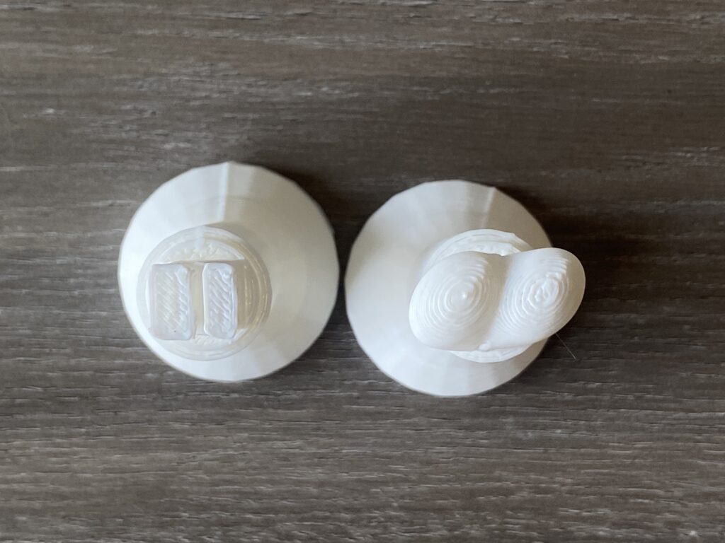
Gear Pin Orientation Issue
When modeling, I initially overlooked the orientation of the gear pins. As a result, I created two gears with different orientations—one with pins parallel to the turntable and the other with pins perpendicular to it. Eventually, I had to remake a set of large and small gears with a consistent pin orientation.

Limited Iteration Due to 3D Printing Time
3D printing takes a considerable amount of time, which significantly limited my opportunities for trial and error. Unsurprisingly, both the 3D printer and I made mistakes during the process.

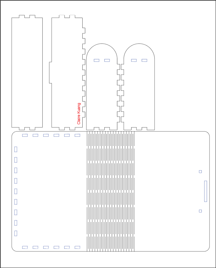
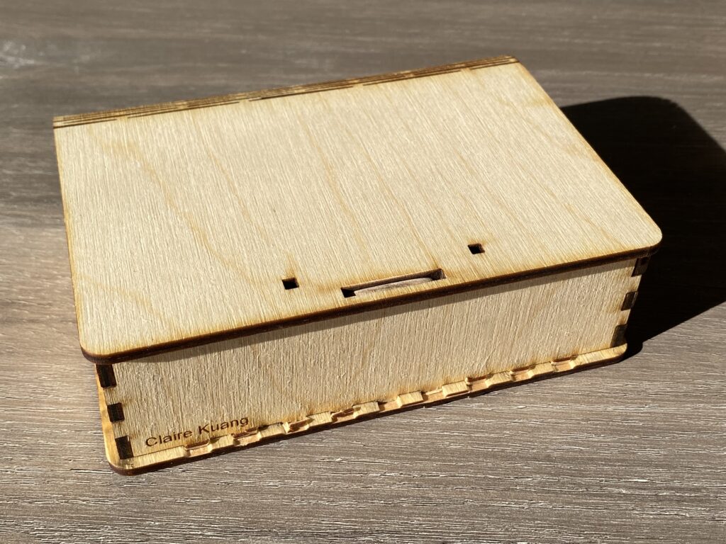
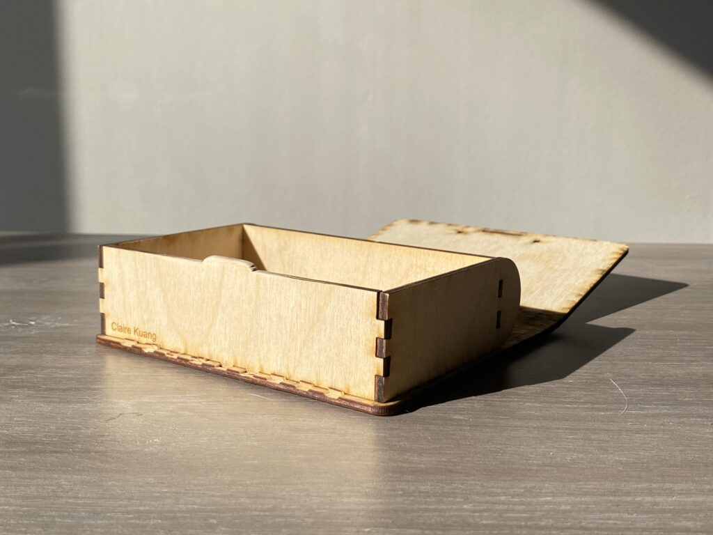
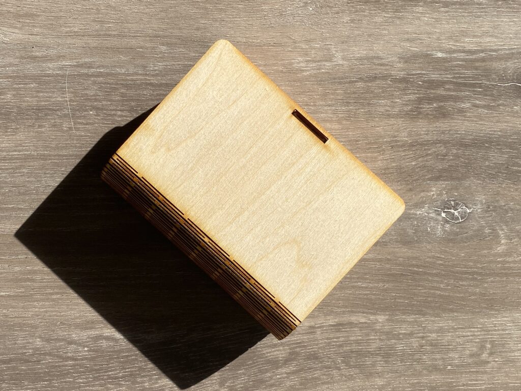
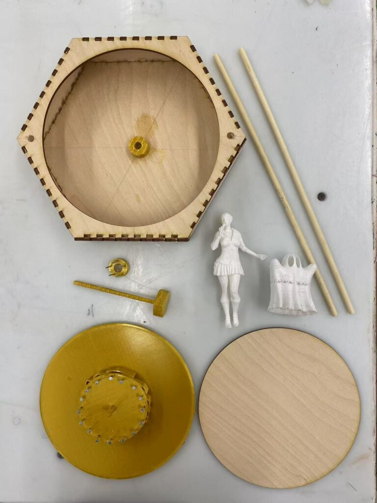
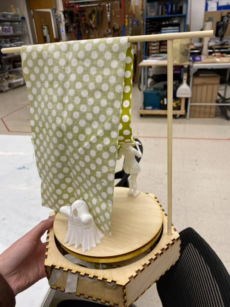
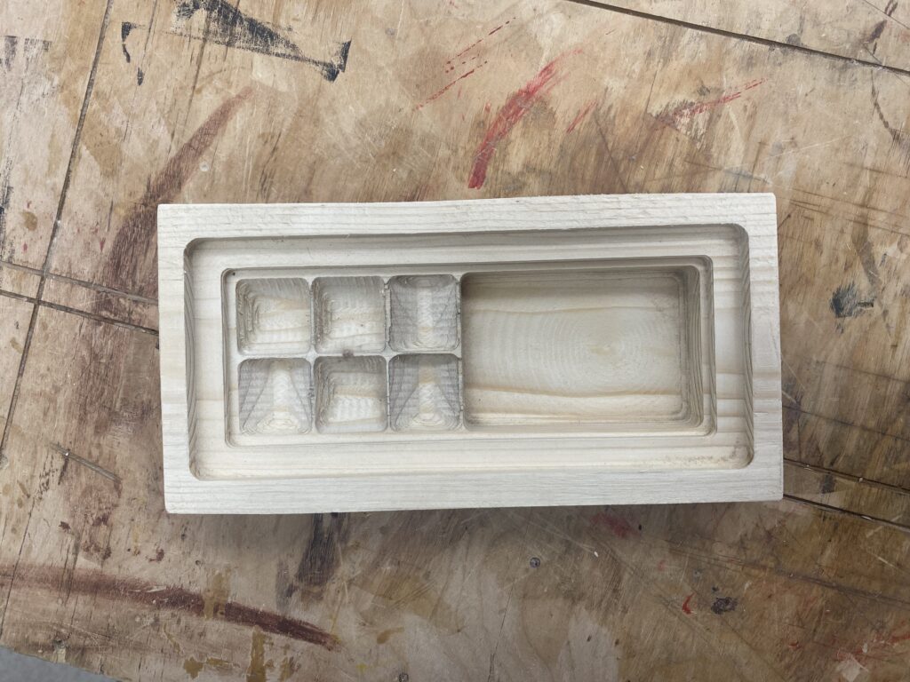
Stage Construction Setback
My original plan was to 3D print the stage structure as well. However, midway through printing, the machine ran out of material. Given the time constraints and the risk of further 3D printing failures, I had no choice but to switch to laser-cutting. I ended up constructing a hexagonal stage box with a circular cutout on the top.

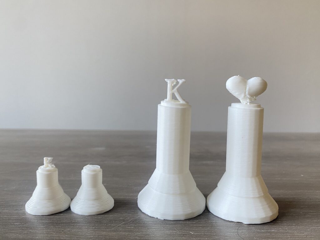
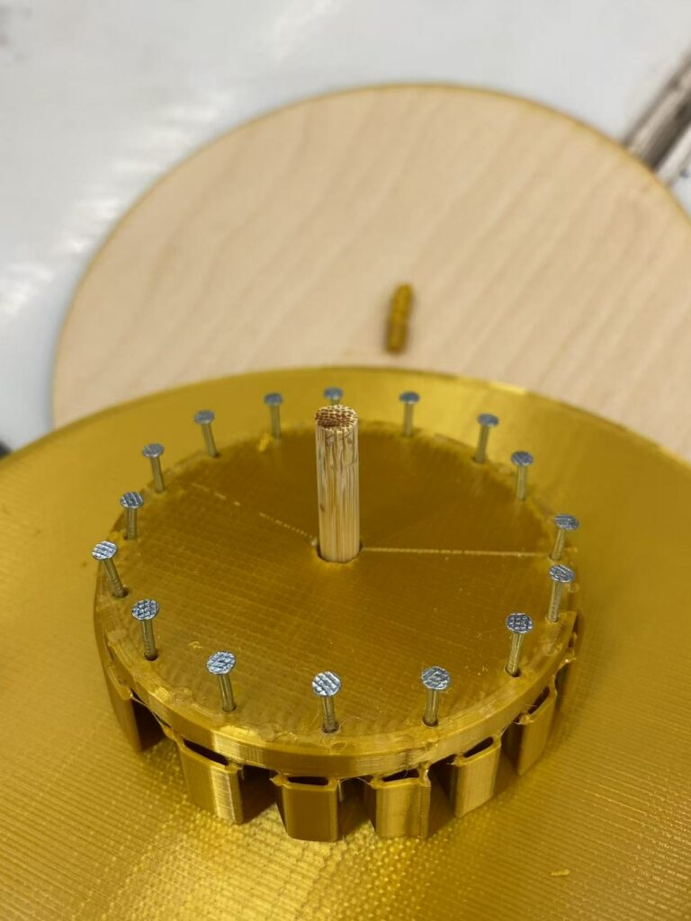
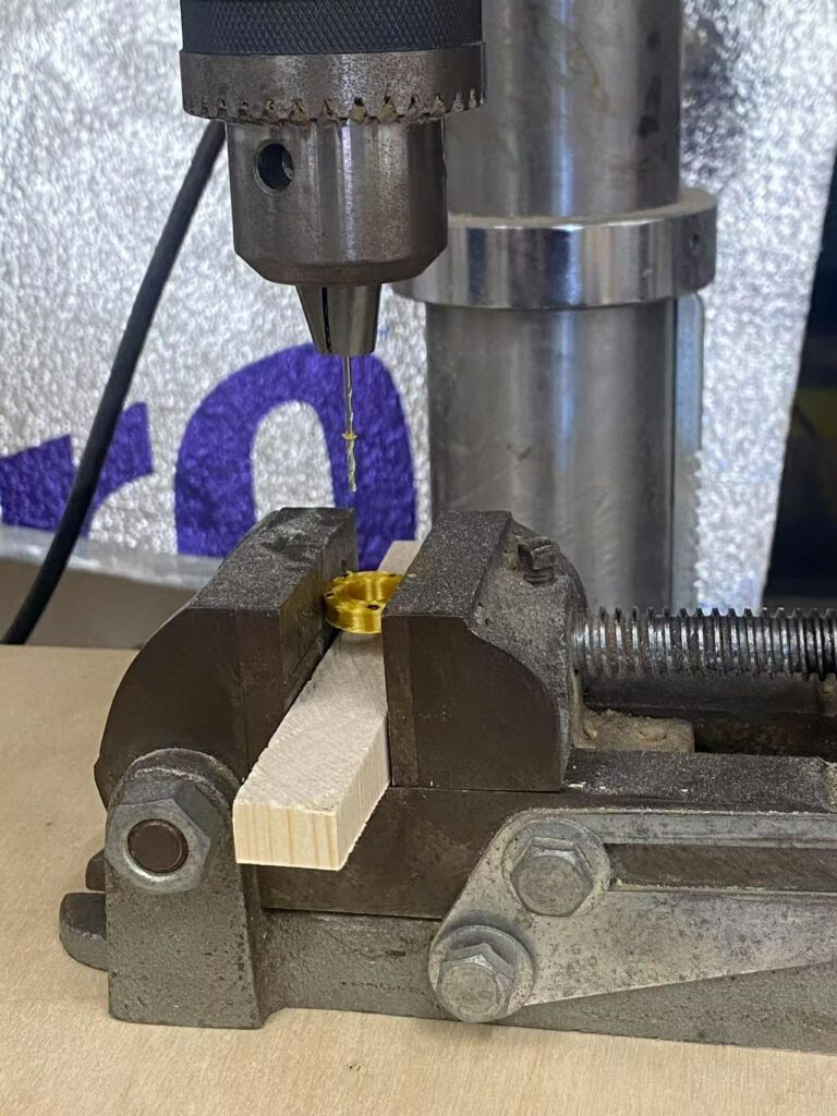
3D Printing Precision Issues
The lack of precision in 3D printing—especially since I used a machine with a large nozzle diameter—led to rough and imprecise gear pins. The supports between the pins were difficult to remove cleanly. Additionally, due to the softness of the 3D printing material, the gear pins did not attach firmly to the turntable. Nearly all the pins detached, forcing me to remake the gears. I ended up removing all the pins from both the large and small gears and reinforced them using woodworking techniques by drilling and inserting new pins.

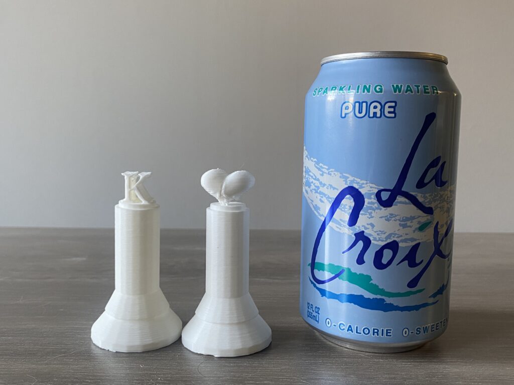
Small Gear Inefficiency
The small gear’s radius was too tiny, leaving insufficient gaps between the pins, which prevented it from effectively rotating the large gear at the base of the stage. I had to redesign and laser-cut a new small gear, then drill and insert new pins. Additionally, the central axis of the large gear at the stage’s base came loose, so I replaced it with a small wooden dowel using a drilling technique.

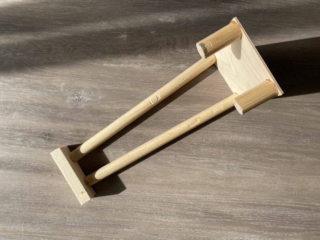
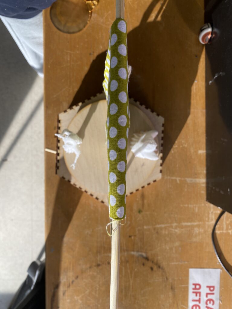
Handle Breakage Issue
I originally 3D-printed the gear handle, but due to the softness of PLA material and the handle’s slender shape, it eventually snapped. The repeated application of hot glue to attach it to both old and new gears further weakened it, causing it to melt. In the end, I quickly replaced it with a wooden strip as a makeshift handle.

Future Improvement

Enhancing the Handle
The current handle is a thin wooden stick, which lacks a strong grip. A better alternative would be to laser-cut a handle with a more ergonomic design for improved control.

Improving the Stage Curtain
The current stage curtain is too stiff, causing it to rotate along with the character’s movements. To resolve this, I could use a softer fabric or secure the bottom center of the curtain with a wire to keep it in place.

Adjusting the Stage Height
The stage box is not tall enough, which required me to elevate the stage surface afterward. As a result, some parts of the stage are raised unevenly, affecting its appearance. A taller stage box would prevent the need for additional adjustments and improve aesthetics.

CNC Custom Wooden Tray

I wanted to design a jewelry box, so I started by researching similar products online. To better fit the layout of my desk, I decided to stick with a rectangular shape rather than experimenting with more complex forms. One issue with my current jewelry box is that large earrings don’t fit well in standard cubes, which prevents the lid from closing properly and leads to dust accumulation. However, I still need regular cubes to keep smaller earrings organized.

So, I designed the box with six small standard cubes on one side, and left the other half as an open flexible space for larger earrings. I also added extra depth at the top of the box to accommodate a future lid insertion.

To implement this, I first created a regular rectangular body and hollowed it out. Then, I added another rectangular solid inside the box and shell-cut it to a shallower depth to reserve space for the lid. After that, I created six 3×3 square components inside the box, hollowed each of them individually to form six small storage cubes. To preserve one of the advantages of my current box—curved inner edges that make it easier to take out earrings—I also added fillets at the bottom of each small cube.

Since the design involved multiple components, I broke the toolpath generation into five steps: cutting the overall box, carving the top recess for the lid, milling the six small cubes, shaping the open flexible area, and finally creating the bottom fillets.

After hollowing out the six cubes, I came up with an additional idea—to raise the bottom of each cube slightly so that I could more easily reach earrings without having to dig deep into the compartments. However, I realized that the 2D adaptive clearing tool didn’t support this kind of depth change, so I switched to the 3D adaptive clearing instead, allowing Fusion 360 to automatically calculate the toolpath for me. Fortunately, the job ran smoothly without major issues—I even increased the feed rate to 150% to speed up the process.

Explore more

Avatar “Masked Lungs” for Class Fundamental of Technologies

css.php